Introduction
How are photocells verified for their durability and endurance? Sourcing photocells for street lighting projects means more than comparing spec sheets. A photocell that looks correct on paper but hasn’t been rigorously tested against real failure conditions will create maintenance problems in the field.
ANSI C136.10 testing is the standard that separates products built for long-term outdoor service from those that aren’t.
For procurement teams and distributors evaluating suppliers, knowing which failure modes the standard targets gives you a much clearer picture of what a passing test result actually means.

What Does ANSI C136.10 Testing Actually Look For?
ANSI C136.10 testing is structured to expose the specific failure modes that end photocell service life prematurely, covering mechanical, electrical, environmental, and sensing performance under conditions that simulate years of real outdoor operation.
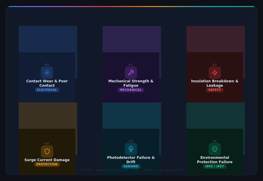
The standard doesn’t just verify that a photocell switches correctly on the day it’s tested. It applies accumulated stress, such as repeated switching cycles, surge events, temperature extremes, and sustained water and dust exposure, to find the failure points that only appear over time.
The six failure modes below are the ones that testing most consistently brings to light.
1. Contact Wear and Poor Contact
Contact degradation is the most frequent relay failure mode, and it’s a direct consequence of the switching function a photocell performs every single day of its service life.
Every time a photocell switches, the relay contacts open and close under load. That action creates a brief electrical arc. Across thousands of cycles, this arcing causes contact surfaces to oxidise, pit, and burn; gradually increasing resistance until the switch either welds shut (light stays on permanently) or fails to close (light won’t switch on at all).
What testing checks:
- Contact resistance measurements before and after lifecycle switching tests
- Visual inspection for oxidation, pitting, and surface burn damage
- Zero-crossing technology reduces arcing by switching only at the zero-voltage point of the AC waveform, directly extending contact life
For buyers, a photocell with verified contact wear performance has demonstrated relay integrity across thousands of real switching cycles. A sound example is the Long-Join’s JL-207C, which uses zero-crossing technology.
2. Mechanical Strength and Fatigue
Internal mechanical components such as springs, actuators, and bimetal elements are subject to cumulative fatigue that builds invisibly across the photocell’s service life until a component cracks, deforms, or jams.
A mechanism that functions correctly at 1,000 switching cycles may fail at 8,000. Fatigue failures are particularly problematic because they don’t announce themselves; the performance just degrades gradually until the switch becomes unresponsive or locks in one position.
What testing checks:
- Full lifecycle switching tests at rated load and temperature
- Torque and force measurements on twist-lock mechanisms across the full cycle count
- Physical inspection for cracking, deformation, or loosening of internal components post-test
3. Electrical Insulation Breakdown or Leakage
Photocells operate at mains voltage in outdoor environments. Insulation failure is a safety issue, not just a performance issue, and it is non-negotiable for any product going into public infrastructure.
Prolonged high-voltage stress, moisture ingress, and thermal cycling all degrade insulation materials over time. Manufacturing defects in insulation thickness create weak points that hold initially but fail under sustained operating conditions. Leakage current from degraded insulation creates a shock hazard and can damage connected equipment.
What testing checks:
- Dielectric withstand (hi-pot) testing at voltages significantly above the rated operating level
- Insulation resistance measurement to confirm that the leakage current stays within safe limits
- Testing conducted at both ambient and elevated temperatures to cover worst-case operating conditions
4. Surge Current Damage
Lightning strikes and grid switching transients generate voltage spikes that can destroy unprotected photocell components in a single event, and without adequate surge protection, even a well-built relay is vulnerable.
Direct and indirect lightning strikes, utility capacitor switching, and large motor startups all generate transients that travel along supply lines. A photocell without properly rated surge protection can be destroyed by any one of them. In smart city and networked lighting applications, a surge event that takes out an unprotected photocell can also damage the connected LED driver and disrupt network nodes.
What testing checks:
- Surge immunity testing using standard waveforms (1.2/50μs voltage, 8/20μs current) that simulate lightning-induced transients on power lines
- MOV (Metal Oxide Varistor) clamping voltage accuracy and energy absorption capacity
5. Photodetector Failure or Drift
A photocell whose sensing element drifts doesn’t fail visibly; it just starts switching at the wrong times, creating chronic performance problems that are difficult to diagnose across a large installed fleet.
UV exposure degrades photoresistor materials over time. Temperature cycling shifts phototransistor characteristics, moving the lux threshold at which switching occurs. Lens contamination (e.g. dust, road film, insect deposits) reduces effective sensitivity without any obvious sign of failure. The result is lights coming on too early, staying on past dawn, or flickering in environments with mixed light sources.
What testing checks:
- Sensitivity measurements at defined lux levels before and after environmental stress tests
- UV ageing tests to simulate long-term outdoor exposure
- Temperature coefficient testing across the full rated operating range
- IR-filtered phototransistor designs improve stability by blocking infrared-heavy sources that cause false switching
6. Environmental Protection Failure
IP rating failure is one of the leading causes of premature photocell failure in outdoor installations. A single moisture ingress event can cause corrosion, short circuits, or component damage that ends the photocell’s service life years early.
Gasket compression set, UV-induced housing brittleness, and poorly sealed cable entries are the three main ingress paths. IP54 protection is not adequate for fully exposed outdoor positions, so IP65 is the minimum for any photocell subject to wind-driven rain or direct water exposure.
What testing checks:
- IP65 dust test: talcum powder chamber under negative pressure
- IP65 water test: 12.5 litres per minute from a 6.3mm nozzle, all angles, minimum 3 minutes
- Post-test internal inspection for moisture, condensation, and dust contamination
- Gasket and housing material assessment after UV and thermal ageing cycles
Conclusion
ANSI C136.10 testing targets the six failure modes that most reliably end photocell service life before its time. For procurement teams evaluating suppliers, a photocell that has passed rigorous testing against all six is a product that has been built with those failure modes in mind. This is evident in the photocells in Chiswear’s catalogue. That’s the difference between a photocell that performs on the spec sheet and one that performs on the pole.
External Links
- https://en.wikipedia.org/wiki/Electric_arc
- https://en.wikipedia.org/wiki/Dielectric_withstand_test
- https://en.wikipedia.org/wiki/Photoresistor
Post time: Apr-30-2026